
RoboClock - An digital clock with analogue movement
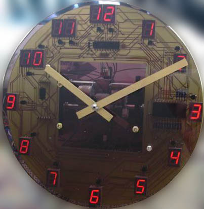 Roboclock is my third AVR based clock. It's not quite finished yet and still half on the breadboard. It is a digital clock with a true analogue readout. The hands are driven by two individual stepper motors which allow me to place them anywhere around the face of the clock with 0.5 degree precision. At the push of a button this clock will show on the same face what the current room temperature is and also by pushing another button, what the humidity is. It does this by changing the numbers around the face to range from 0 to 9 starting with zero at the twelve o'clock position and blanking the 10 o'clock display. It then moves the hands accordingly. Say for example it is 18 degrees, it will move the hour hand to the 1 o'clock position and the minute hand to the 8 o'clock. The 11 o'clock display changes to a 'C symbol. The same is true for displaying humidity, except the 11 o'clock display changes to 'rh' to indicate relative humidity which is read off the hands in a percentage. I got the idea for this clock after seeing a Tissot t-touch watch that does pretty much the same thing with its hands. I thought it would make an interesting project to have a play with driving stepper motors and also positioning them accurately whilst also having to build some mechanical parts and needing sensors for feedback. An ideal starting point for getting into robotics, this clock realizes some of the challenges that await me in that field.
The Clock consists of three main parts:
1) The mechanics for moving the hands.
2) The main control electronics for time keeping, measuring the environment, and driving the motors.
3) The electronics for driving the 7 segment displays behind the smoked Plexiglas face.
The first thing I started work on was the drive mechanism.
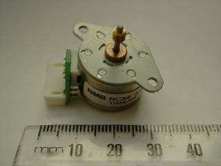
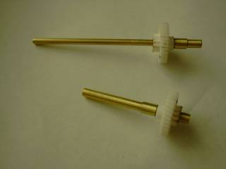
They came with a little brass worm drive crimped on the output shaft which I filed off and replaced with a gear. The first prototype drive I made was pretty much a single reduction direct drive. using a 3:1 reduction with gearing I could get a 6 degree per step resolution. 6 degrees is how much a hand must move on a clock face to shift 1 minute.
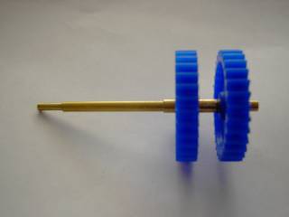
The shafts are made of brass tubing which fits nicely into itself.
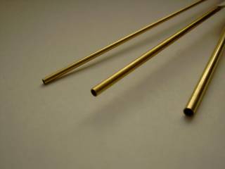
These shafts are made by K&S Engineering of Chicago. I bought them at the local hobby shop. I got three sizes, the smallest for the minute hand, next size up for the hour hand, and next one up for bushings and spacers. Fitted together coaxially it makes a nice drive for the hands. However as is generally the case with prototypes, design flaws are highlighted and one major flaw I had was that, because my clock hands were made of brass strip, the clock worked quite well lying flat, but as soon as I held it up, the little steppers didn't have enough lock on their own to hold the hands in place and both hands drooped to the 6 o'clock position. This could be counter acted by applying current to the motors at all times and therefore locking the motor armatures in place, but this created heat in the motors and drive electronics, plus required constant current draw. So the search went on to create a better mechanism.
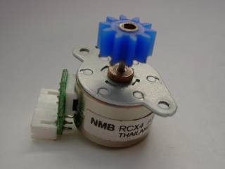
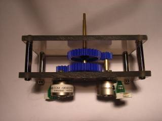
This search didn't last long as I found what I needed in the form of a worm drive gear. The gears and worm drives also came out of a copier. (handy that, working in the copier industry) I replaced the gears on the motors with the worm gears and mounted the motors so that these worms gears are engaged with gears on two coaxially mounted shafts.
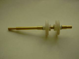
The ratio of the worm drive to the gear is 35:1. This works out very nicely as it gives me 0.5 degrees per step resolution which means I need to step 12 times for one minutes worth of hand movement (6 degrees) and every minute worth of movement the hour hand needs to move 0.5 of a degree! The steppers are mounted one on either side of the central shaft. Having a worm drive meant that the load of the hands was no longer an issue, so now power is only needed to shift the hands. This is only a short burst every minute
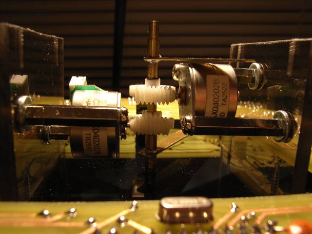
Upon power up the controller has no means of knowing where the hands are, so I fitted two positioning flags that pass through photo interrupters These can be seen in the above picture just below and above the right motor.
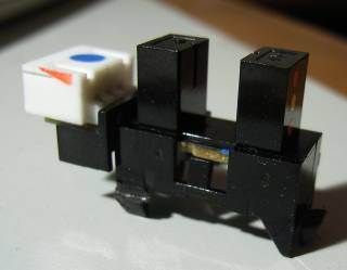
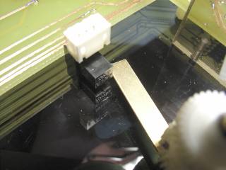
The photo interrupters are standard Omron equivalent types. The flag breaks the light beam as it passes through. The first task the processor has after initializing the display is to move the hands so they are definitely clear of the sensors. It then rotates the minute hands around the clock until its sensor is activated, followed by the hour hand. The processor now knows where the hands are and they are moved to the 12 o'clock position and the 'time adjust' routine is entered.
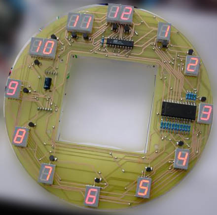
The display controller is run by a AT902313. Its job is to display the correct information on the 15 seven segment LED displays. I originally started with a system that basically had a separate memory for each display by using a data latch (74LS373) and having it controlled by the main processor. I had it configured in a addressable bus system. The same data port on the main processor was used to drive the motors and displays and a separate port for addressing. The problem with this again was current consumption as each display was on at all times and each one had its own data latch. A much better way was to multiplex the displays as most displays are. I stumbled across the new 'Charlieplexing' method on the web but after reading the articles about that I decided that that can be a future project when I am a bit more clued up :-). I decided to use a separate controller for the multiplexing of the displays so that there wouldn't be a flicker when the main controller is doing motor or ADC tasks. The two controllers talk to each other using a logic level two wire Rs232 link. Each time I want something new on the display I just send a string out through the serial connection and the display controller handles the rest. All segments on the displays are individually addressable, as in, I am not limited to numbers. See the schematic for the display board here - DisplaySchematic.jpg
I was keen to see what the whole thing looked like mounted up behind the smoked Plexiglas face so I etched my first ever double sided board. The diagrams and board layout were done with Eagle. Many attempts were made to try and fit it on a single sided board but in the end we settled for a double sided board. The track layout was printed onto the board using "Press and Peel" film fed through a laser printer and ironed onto the copper clad board. Lining the two sides up was a bit of a challenge but I managed to do it and etched my first ever computer routed PCB.
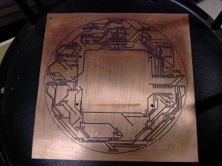
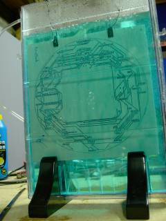
The board with the "Press n Peel" tracks applied and the board in the etching tank.
The main controller consists of a ATmega16 running of its own internal 8MHz clock, It has connected to its ADC ports the temperature sensor (LM35) and a humidity sensor (A TDK CHS-MSS). There's 3 buttons for controlling the clock, and the inputs for the hand sensors. The Motor drive is done through a M54585 driver chip from Mitsubishi. It has its own dedicated port and both motors run off the same IC, the low 4 bits for the minutes and the high 4 bits for the hour. Connected as well is the 32.768 kHz crystal for timekeeping. I still haven't decided what I am going to use for controls for the clock, ideas so far have been infrared, sound, touch, proximity. I am also contemplating having a pendulum and maybe an hourly chime.
Here's the control board schematic so far: controlschematic.jpg
More to come... this project is still in the making...
Here is some video of it working so far