The Nismodore
Well, after my V8 Commodore got stolen, I thought, shall I build another car and have it nicked, or shall I buy a car and have it nicked.
I first went with the buying idea. I thought about WRX's, too common. Evo's? Too common. Skylines? every man and his dog has one. I test drove Series 7 RX7, Mitsi GTO's, Toyota Soarer/Lexus SC400's. 300zx's yeah... nah... too common. (your probably thinking commodore's are common too!, read on) I was quite hooked on the RX7, and thought it would be cool to own a rotary for once, but not knowing anything about them and the fact that they can be expensive to soup up steered me away from that. The GTO was a brick, and they have weak motors. The SC400 was too smooth. so... what can I do....
Lets build something different!... I seriously looked into buying a Lamborghini Diablo kit from the states but the end cost would be high. Then came the Lada 2104 with a SR20DET or a VR4 motor in it. But that could be a bit difficult to certify. Then the commodore Idea sprung back into mind. I thought about doing this when I first blew the motor in the V8. But then it was with a RB20DET.
The more I thought about it the more I liked it... so much in fact I started lacking in sleep. First came the RB20 turbo idea. then the full on Godzilla RB26DETT 4wd 4ws Idea. That really got the ball rolling.
The search for info and a motor was on. I talked to people and one mechanic suggested the RB25 over a RB20. So I rang around for either a RB26 or a RB25, no-one could supply me a RB26DETT so I settled for the RB25DET.. after all its only 100cc's and a turbo off. Parts Imports up in Auckland had a RB25 on its way from Japan for stock. So I put my name on that and had about a month to find a car!
The search was on... after looking at many rusty and clapped out examples, I stumbled on the perfect candidate. Picked it up for a steal and waited for the motor to arrive.
Read on and see how a sedate commodore can be turned into a tarmac tearing V8 beater! :-)
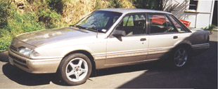
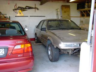
As these photos show the Nismodore started life of as a stock standard Holden Commodore Vacationer
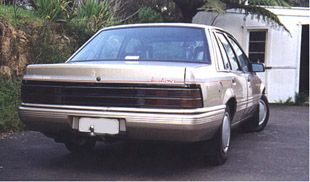
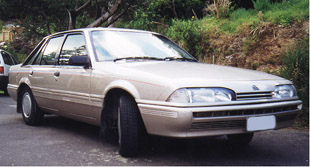
As far as I know, these are a New Zealand only model commodore. They came fitted with a 2 litre 6 cyl OHC Nissan engineered motor, also known as a RB20E. The drive train consisted of a 3 stage auto with lockup torque converter or a 5 speed manual , both Nissan made as well.
Because of the two litre a final drive of 4.11:1 was fitted.
Luxury features fitted were electric mirrors and the seats are a bit more hugging. More like those out of a later model commodore like a VN
The very first thing that got bought for this car was a kick-ass alarm. You step near the vehicle, the alarm warns you of its guard. No I am not going to tell you what type of alarm it is. :-) The other thing that got purchased at the same time was a Sony CD head unit, AWA-Clarion front speakers and tweeters and some Cadence 6x9's in the rear. The whole lot doesn't sound to bad for what it is.
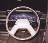
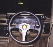
The same week we also got a Racing Line Momo steering wheel, like I had in the V8. These are awesome wheels.
Next we got a set of second hand mags. I needed at least 15" mags to fit the brakes that I wanted to put on and these 16"ers were up for grabs when I was looking around the wreckers yard for a disc brake rear end. I also picked up some bonnet struts out of a VR commodore. Its amazing what you learn when you do things a second time round. The VR bonnet struts are the same as what HDT sells as VL struts.
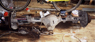
Here's a pic of the diff and the VR V6 front brake calipers that I got from a different car wrecker.
Soon after getting the diff and the calipers I also got another full set of DBA cross drilled and slotted rotors. They went on the weekend after I got them along with the diff going into the car.
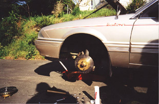
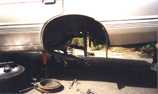
Quite a productive weekend that one... :-)
The motor, gearbox, computer and airflow meter arrived on a pallet from Parts Imports. These guys gave me really good service, I recommend them if you need to get hold of a motor or gearbox or anything.
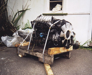
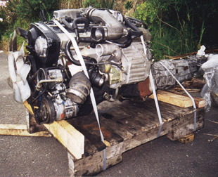
I stripped all the redundant bits off the motor whilst it was in this state, like the air con and power steering pumps.
The weekend after the motor arrives we start pulling out the old 2 litre
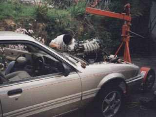
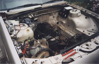
The next day we fit the RB25DET. Unfortunately I have no pictures of when it just went in but the motor sits on all the original Holden engine mounts and the gear box in its original mount. The Holden mounts bolted straight to the block and a Holden 3 litre VL drive shaft was fitted in the back of the gearbox. No modification needed. I found the inlet manifold to be a bit close to the larger brake booster so I spaced the engine to the left of the car with a 5 mm alloy plate fitted in the right engine mount. I made up a gear stick out a Holden 5 speed item and a high chrome steel shaft out of a photocopier. Nice firm and short shift and the shaft wont rust. All boots around the gear stick are holden items. The Holden power steering unit bolted onto the motor no worries.
I spent about 2-3 hours every night for the next two weeks wiring up the loom.
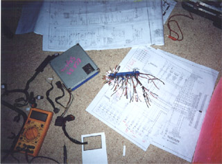
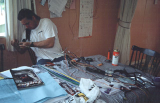
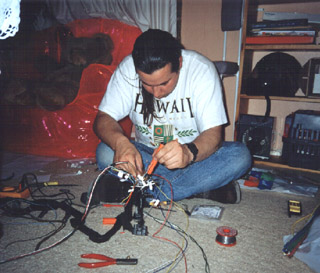
The problem with a RB25DET is that it was classed a domestic motor only and therefore not exported outside of Japan by Nissan. This meant that finding wiring diagrams in English was near impossible. City Nissan here in Wellington got me the diagrams for a complete RB20DET engined R32 Skyline in English and in Japanese and for the RB26DETT in English and for the RB25DET in Japanese. Well, I cant read Japanese for starters and car circuit diagrams are a nightmare at the best of times. But I started comparing Japanese symbols between the English/Japanese and the Japanese only 25t diagrams. Soon I figured out where the important bits were like the Airflow meter, Oxygen sensor, Crank angle sensor and the spark plugs. Then the next problem came along. The plug that was supplied with the computer fitted, but it sure wasn't the one for the 25t. So that plug was disassembled and all the wires changed around to suit. So after well over 100 solder joints and heatshrinkings the loom was complete and fitted to the vehicle. There was then some work to connect everything up to the ignition system and speed sensors. For those of you electrically inclined the loom consists of different gauge wires and shielded coax.
The time came to fire it up.
Checked all the preliminaries like oil and water, electrical connections etc and turned the key to ignition. The fuel pump turned on and built up pressure then stopped. This was good. The car didn't have an exhaust at this stage and all my mates were standing around with their hand over their ears as I preceded to crank it. Well, it cranked! that was also good. Then it started to fire once in a while emitting loud popping noises from the short dump pipe of the turbo. Give it a bit more gas, and there is was, It started! but it ran like it had anti-lag. the turbo was winding up and boosting, it backfired and ran rough. A bit of a stab on the gas pedal saw it run smoother but settle back down to the popping and farting. I shut it off and checked a few things. Pulled off the temporarily mounted intercooler and oil gushed out of it. My hopes fell on the floor at that point but we decided to see if it was just oil sitting in the turbo from the trip over from Japan. We hooked the airflow meter straight to the throttle body, bypassing the turbo and started it again. Holding a rag to catch the oil we found out what a couple of pounds of boost coming out of a turbo felt like! :-). Eventually no more oil came out and we hooked the turbo back into the circuit, started it, only to find the same thing again. Out came the wiring diagrams, I checked everything over. Then it came to me, The injectors were labelled 1-6 as per cylinder layout, but the coils were labelled 1-6 but in firing order. I quickly re-wired the coil part of the loom at the computer end and reached for that key again. This time she started straight away, rose up to about 1500 rpm, sat there for about 10 seconds and settled down to 1200!. I tell you, after 4 weeks of pulling and fitting motors, making wiring and stabbing in the dark, I was overcome with emotion. Tears of joy rolled down my face as this engine sat there idling smoothly and eventually sitting peacefully at approx 800 rpm once it warmed up a bit. I could not believe I had actually done it!
If the drive to completion wasn't strong enough before, it was even stronger now. I had to have an intercooler. So purchased a standard R32 intercooler along with all the piping and exhaust dump pipe to get the flange that bolted up to the turbo. Using the standard intercooling piping and some extra 2.5" tubing I set upon to make the intercooling pipe work. I made it so that I could fit almost any size intercooler I wanted under the front. Here's a pic of the piping after it came back from the sand blasters (to get rid of any welding flake). Looks like any type of trust or HKS intercooler kit if you ask me, just this one is GSR! (Guido Seevens Racing) :-)
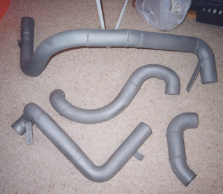 You'll see further along how these fit and how I got a bigger intercooler in.
I also made up the exhaust to fit onto the standard 2 Litre vacationer 1 and a something or rather inch pee shooter exhaust so I could drive it. The first piece of the Nissan exhaust that I used seemed like it was made to fit a commodore. It hugged the profile of the floor pan nicely. Well. the moment of truth came and I rolled the car out of the garage to take it for a test run. Couple of runs around the block to test everything was bolted in right and to warm it up, then stab that throttle to really test if everything was bolted in right. Upon boost a rather harsh mechanical screech came from under the bonnet, but only under boost. All sorts of things passed thru my head at that moment, from blown turbo's to stuffed crank bearings. Turned out that the bolts that held the turbo on the manifold weren't tight and there is a metal gasket or two between them that was being played by the motor like a reed!. Tightened those bolts up and all was well. Didn't go as well as I expected but then I still had a pee shooter exhaust that hissed like a compressor on heat! :-)
Well, I guess you're probably eager to see how it all looks under the bonnet, so here are some pics
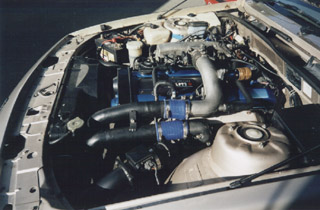
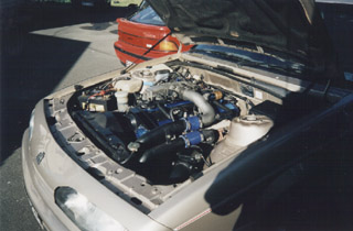
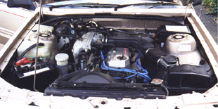
Please note that these pics were taken well after the original fitting as I didn't take any pics then. These show how I painted the rocker covers and how the coil cover looks with carbon fibre film stuck over it and a Nismo sticker. You'll also notice on the bottom left an absence of a air filter. well.. this was mounted under the bumper for cold air, more pics of that later, this was simpler than building a could air box. On the firewall you'll also see the black and silver compliance plate for Low Volume Vehicle Certification. Something that's required in NZ if you modify a car like this. Also fitted is the turbosmart Type II blow-off valve. It generates a sound that makes people look twice at the Nismodore.
Also manufactured now is a full 2.5" mandrel bent exhaust with a Cherry Bomb Vortex muffler before the rear axle and a normal V8 issue rear muffler. It gives the car a rather distinctive exhaust note. Not quite a normal six, but not a V8 either, nor does it sound like a skyline.
The Commodore and the Skyline have a different way of implementing the rev counter. Where Commodore gets 6 pulses for every revolution of the motor, the Skyline gets 1. The Commodore gets it from the distributor, the Skyline from the computer. My mate Dave and I made up a circuit to combine all six coil outputs from the computer into one signal strong enough to drive the rev counter on the Commodore's dash. Here's Dave in the drivers seat and me looking at the signals with an Oscilloscope with some bewildered onlookers :-).
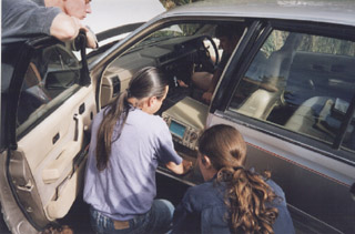
This circuit is now available as a ready made module. Click here for details.
I needed a boost gauge. Here's how I converted the standard dash into a turbo dash
Here's a pic of the standard dash which we fully disassembled
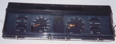
Here's the dash after I cut a hole in the centre of the backing panel and front panels for the boost gauge
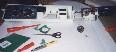
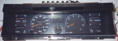
And here is the finished product, with carbon fibre and all. Like a factory item. I even made a custom needle for the gauge.
The need for a bigger intercooler was obvious. I couldn't afford an Apexi or Trust or any of those brand intercoolers so I went for the most popular upgrade one can get. A VR4 intercooler came up for sale and I picked it up for a snitch. Took it down to Kia Ora Engineers and got some 2.5 Alloy pipes welded on to it along with some brackets. If I had a MIG welder, I would have tried it myself.
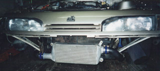
Not something you see mounted to just any Commodore :-)
And as it hides behind the bumper
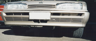
After I had been out on the drag racing track scaring the willies out of some V8 owners I realised that I couldn't hear what my smooth running little six cylinder was doing. All the V8 boys run open headered. Why not do the same on the Nismodore. That's where this 3" creation helps.
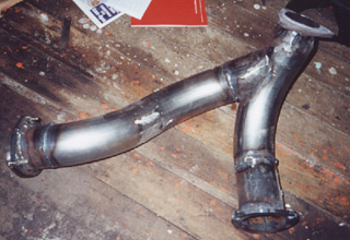
Top right connects to the turbo, bottom right to the tailpipe and the left side comes out just behind the left front wheel. Undo 3 bolts from the flange and one has open exhaust. Instant Noise and Power.

Here is how the turbo sees it, top left going to the rear, right hand the flange. I put a torch into it to highlight the split.
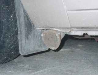
And here is how it looks under the car, with the flange in place
The plan is to run a 3" exhaust all the way to the rear. But as yet I haven't had the urge.
All cars get it at some stage (unless they are plastic or alloy), that dreaded cancer, Rust.
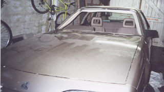
As with any VL, mine had rust around the windscreen. Luck or bad luck had it that a stone hit my windscreen and placed a big crack in it. After some consultation with State Insurance I asked if I could do rust repairs in between the windscreen being pulled out and replaced. They were fine with that so heres a pick of the car in a sad state
To make the brakes firmer I made up a booster support bracket. Get a friend to push on the brake pedal for you whilst you look at the booster to see how much it moves. With the commodores this movement is about 2-3 mm. That equates to a bit when you add in the leverage effect of the pedal.
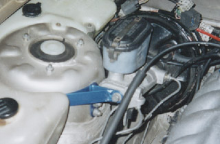
The paint I chose for this bracket actually dictated the colouring of the other detailed parts like the rocker covers and accelerator cable bracket. It was such a wicked blue that it ended up everywhere.
Its time again to make the car look mean and get rid of that ugly big eyed front just like I did to my V8 Commodore
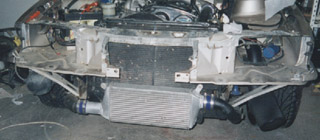
The front with all necessary bits removed
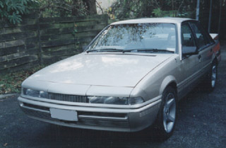
And new bits fitted! :-) Here you can also see the 17" Clubsport replica rims I scored. I didn't have a group A grille to fit but that will come in time.
The turbo dash was cool, but White faced gauges are the trend. Not being able to purchase a white faced dash for a VL at the time I proceeded after many weeks of thought to make a new dash.
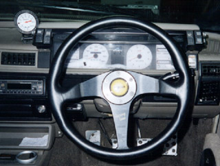
The beauty of printing your own dials means you can do what you want with them
here are some pictures of the prints I used

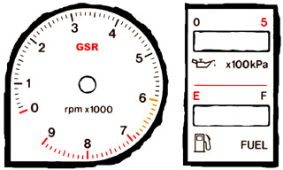
I surrounded the gauges with carbon fibre stick on film. The GSR of course stands for Guido Seevens Racing. The Speedo has been roughly recalibrated so that it matches with the speedo drive out of the Nissan gearbox (My 100k is where a standard commodores 80k is) And the top end brought up from 200 to 240. The rev counter has been extended to 9 grand (tho the motor is limited at 6800rpm). The whole lot was printed on high quality white paper with a colour photocopier. The paper was then stuck to 0.5mm thick white Polystryrene sheet behind which I stuck 2 layers of blue cellophane so that the dash has a blue glow at night. This is to be replaced by Electro Luminescent sheet which will give it the Indiglo type effect. The gauges will then be printed on transparencies. The satellite switches and boost gauge have been illuminated with blue LED's
At some stage I am going to fit a surge tank and I read that once a surge tank is fitted that the constant pumping of fuel can heat the fuel up. Naturally the cooler I can keep the fuel the better. So I set about to fit a "fuel Intercooler" :-)
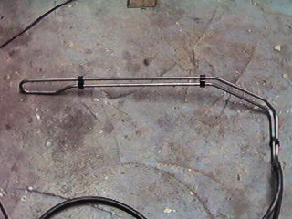
Here is a pic of the fuel cooler. Look familiar? it should do, its a trans cooler out of a VR commodore. I fitted this in front of the vehicle, just behind the bumper.
Then removed the top half of the inlet manifold and first removed the pipe that runs fuel from the front to the back of the motor, indicated by the blue arrow. I then plumbed the fuel inlet hose to the back of the fuel rail as shown by the red arrow. The return hose remains standard as shown by the green arrow. As the throttle body had hot water running thru it to aid cold running. I re-employed the old fuel rail as a coolant bypass.
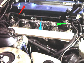
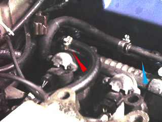
So, now the fuel comes out of the tank, goes thru the cooler at the front, into the back of the fuel rail, out the front of the fuel rail and returns to the tank.
Here is a big bold and plan!
Nissan skylines, Cefiro's, 300ZX's and 200SX's are all fitted with the same type of independent rear suspension. It may vary a bit in width however they all share the same diff head (different ratio's tho) and same multi link setup.
Now, I have never heard of one of these diff's breaking and I have seen plenty of Skylines and 300ZX's doing donut after donut and both wheels going all the time. So I thought it would be wise to fit one of these units to the back of the Nismodore. :-) Its going to be a biggy, but if I pull it off it will be good!. Now the reason I went for a skyline/Cefiro rear end is because a skyline and commodore share the same wheelbase and track!. Also, I have seen a commodore in a magazine with the full GTR running gear fitted! (yes its in the pipeline for me too!. the 4wd at least!). So it can definitely be done.
I'll be posting details of the work as soon as I start fitting it, but in the meantime, here are some pics of the suspension subframe
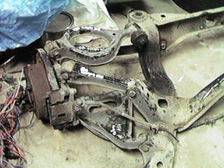
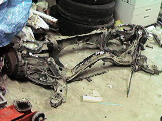
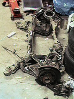
and here is a picture of the 4.36:1 ratio, Viscous Limited Slip Diff head unit.
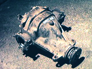
Wish me luck! :-)
Ok, I finally get some time and will power to remove the standard rear suspension, fuel tank, fuel pump, tow bar and anything else that hangs under a VL commodore's rear end so that I can trial fit the Nissan Independent rear suspension, to see if its really worth while.
Most of you reading this page will know what the standard rear end looks like but here is a pic for refreshing your memory, (and mine)
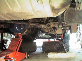
Just the standard 4 link, panhard rod setup.
Once all was removed we jacked the whole Nissan subframe up.
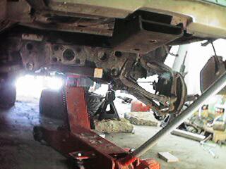
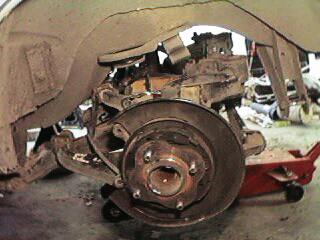
I was totally amazed at how simple this conversion is going to be (well we might hit some rough road but first impressions are good)
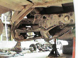
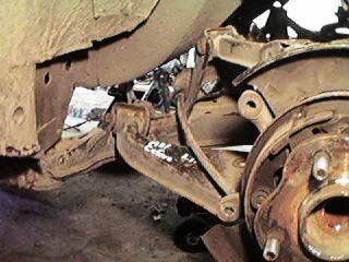
Better than a nine inch?
The Nissan diff is one well constructed unit! I compared it to a VL V8 4 spider unit I have.
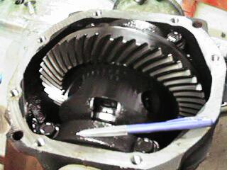

Check out the difference in size! Nissan on the left, Holden on the right. I put a pen in there for reference. The crown wheel on the Nissan diff measures appox 8.5 inches in diameter half an inch off a nine inch that is! :-). Its also got much bigger bearings that the Holden item. According to an article in an issue of Street Machine, the Borg Warner Holden diff is an alternative diff for hi-po street cars.
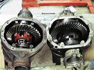
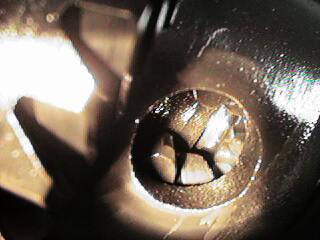
Here's both in the same picture along with a close up of the Nissan's spider gears, of which there are four and the outer ones being like rings with holes in them compared to gears. Hard to believe that this diff was fitted to a two litre non turbo cefiro!
No going back now!
Well, I started cutting out the brackets that hold the original suspension in place. It all better fit in now because if it doesn't I have just ruined a good shell! :-)
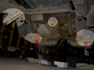

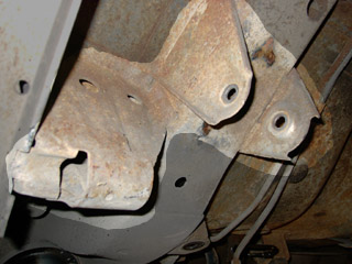
Highlighted are the brackets I targeted first, The Panhard rod mount, trailing arm and jackpoints and the diff bump stop. The panhard rod bracket is of course no longer needed, nor is the diff bump stop. New brackets will be made to fit where the original jackpoints were.
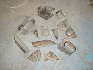
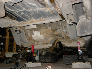
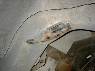
A good weight saving exercise :-). Next step, cleaning up the cuts and making up the brackets and pins to bolt the rear end too.
To hold the suspension subframe in I needed 4 pins. A visit to a Accresent Engineering in Wellington sorted that out.

Supplied them with a simple diagram based on measurements made on the subframe and looking at what Nissan made up. I made them longer at the thread and the top end so that I can cut them to suit.
To make the whole process of fitting the rear suspension easier, I decided to make up a rotisserie for the car. (spit-roast petrol-head style!)
friends and family thought I was mad. except my brother, he agreed that welding upside down is a darn side harder than welding normally. The other advantage is that I wouldn't be trying to defeat gravity by holding the rear end up with jacks and axle stands. With the whole car upside down the rear end can just sit and be positioned using wooden blocks.
First step was to make up mounting points on the car.
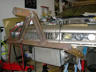
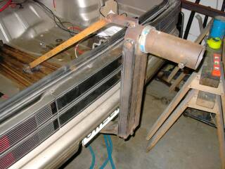
The front mount just bolts on to the chassis where the bumper mounts go. (BTW, the left headlight is out of a Nissan Sylvia S13, something I am looking at doing too as they fit quite nicely in a calais front). The rear bar mounts off an old towbar tongue with some support from the top. If I didn't have a towbar I would have used the rear bumper mounting points.
The next step was to make up front and rear A-frames and get the car up onto them
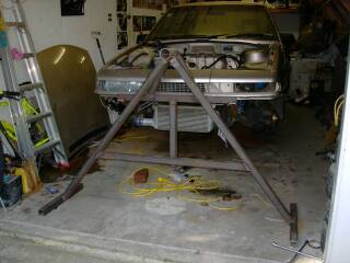
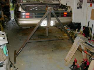
You'll see that I have added some uprights to both mounting brackets. I used the jack under these to get the car up onto the A-frames. The whole thing is basically a big engine stand at both ends.
Then came the turning over...
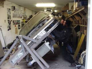
This is when I came to realise that my usual knack of guestamates and getting it right first time failed me. Having no idea where the balance point of the car would be, I just drew an imaginary line. It was a bit too high, and even with five fella's heaving and groaning we couldn't get it past about 80 degrees.
After some modification and lowering the pivot point by 150mm, the car turned over so easily that I could do it by myself.
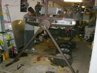
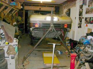
I ended up welding an old flexiplate on the front mount as I was going to make a crank handle, but couldn't be bothered in the end.
With the car upside down I had to tempt fate and Gweed-test it.
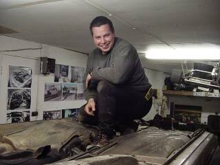
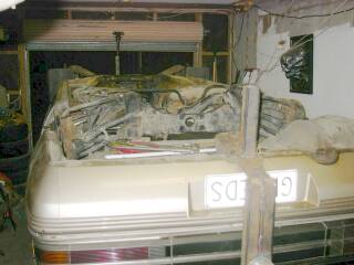
We wobbled the A-frames, walked over the bottom of the car from one end to the other, surfed on top and jumped on top just to make sure its all strong enough. In fact the car is more stable this way than it is on four axle stands. The picture on the right shows the rear suspension just sitting in approximately the right place.
Now that the car is upside down, work on the rear suspension could begin. I layed the suspension on top of the car and roughly positioned it with wooden spacers I then made up platforms for the pins to sit on underneath the mounting points on the frame. After they were in place I cut the pins to the right height and I was able to position the whole subframe accurately as it rested only on the four pins and could slide around within the confines of the platforms. After a lot of measuring and double checking measurements, and satisfied that the subframe was centred and straight, I welded the pins in place.
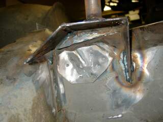
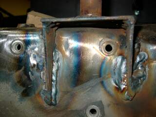
Here you can see the two rear pins on their platforms. These platforms sit in the corners of the chassis rail and the rear cross member. The one on the left still has some metal left from the panhard rod mount and the other is around the holes where the fuel pump used to bolt up.
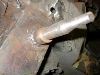
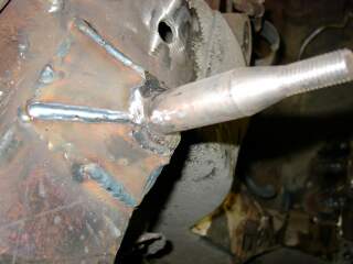
Here is the front pin (the other side is a mirror image basically). They sit where the old jackpoint were. Only after all this did I realise I didn't have to cut the jackpoints back as far as I did. But hey, who was to know eh! :-)
I had a certifier come and look things over at this point to make sure I was heading in the right direction. The only change I had to make is shown in the pictures above. A bit of gusseting to strengthen the front pins. The rear ones are only about 5mm off the platform so they were ok.
With the pins in place I could bolt the sub frame up and check some other aspects.
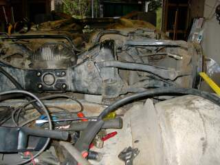
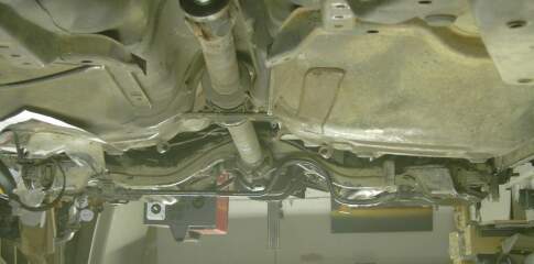
I rotated the pic on the right to be more what it looks like should you be run over by the Nismodore. That's the Holden drive shaft in there too BTW! It needs its flange to be modified to bolt up to the Nissan diff, but the length is perfect. However I am looking at making a one piece shaft to get rid of that centre joint.
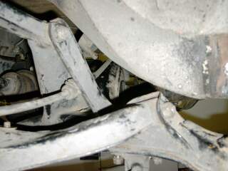
Here's a view looking in from the right of the vehicle. It shows how the commodore chassis rail clears the bottom and top control arm mounts nicely. (again this pic was rotated)
Here are some close up's of the how the subframe sits on the pins. Front on the left, rear on the right

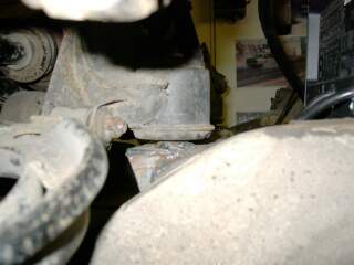
Note that the front pins have since been gusseted as shown previously.
The front mounts have a brace that goes from the pin back to the chassis. A bracket needed to be made up to accommodate this too.
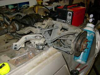
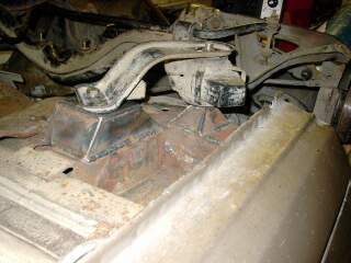
And hey presto! That's how you mount Nissan IRS in a Commodore! :-). Now for the difficult part. Making up spring mounts and finding some coil over shocks/struts to fit.
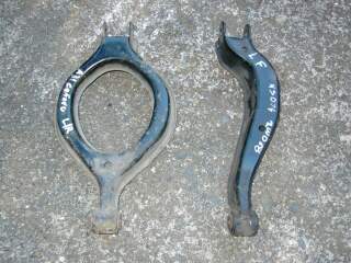
Thanks to the great dudes at New Zealand Car Parts I was able to borrow some suspension components. The Hubs on the Cefiro setup were only 4 stud, and unfortunately the hub flange was a cross shape, not allowing me to re-drill them to 5 stud. GTS-t skylines however have 5 stud, so I picked up some five stud hubs after comparing them with my 4 stud setups. Also, to give me more options with spring mountings I found that the top rear control arm out of a S15 sylvia would suit my needs better. Here's a pic of the differences between the Cefiro/Skyline/300zx top arm on the left and the Sylvia one on the right.
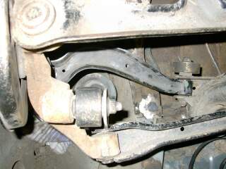
Having only half the arm it gives me heaps of clearance for any shock/strut setup I decide to use. The picture on the right is taken from what would be underneath the suspension looking up. The strut fouled on the original cerfiro arm.
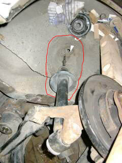 As far as springing goes, it looks like the easiest option would be to get some performance skyline adjustable struts and mount them into a modified shock turret.
The plan would be to cut out the area in red and insert a new piece of 5" tube, into which the strut and spring assembly can sit. For added strength a strut brace would be mounted across the top of the turrets in the boot.
As mentioned previously the Cefiro rear end I got had only 4 stud hubs and the flanges were a cross shape. This configuration didn't lend itself to re drilling to the commodore 5 stud pattern. I picked up some 5 stud hub assembles of a R32 Skyline GTS-T. They have the same axle diameter and spline count as the cefiro's hubs. I had to buy complete assemblies as the wrecker wouldn't sell my just the hubs. Ah well.. spare brake parts I guess :-)
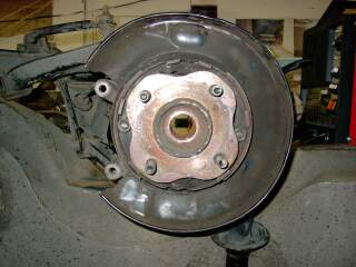
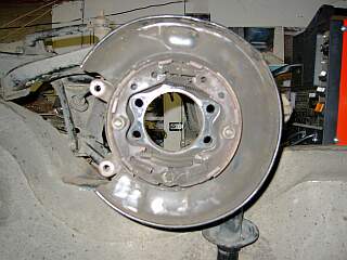
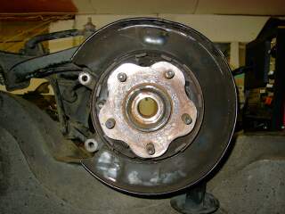
Changing them over was dead easy. 4 bolts in the back of the hub and out it came, then just insert the 5 stud hub and presto! Bob's yer uncle.
The process of re drilling the hubs is a fairly simple one (or so I thought, read on!). First we knock out the original studs.
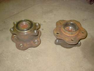
Then I separated the flange from the bearing case so that the bearings and seals would not suffer from the heat induced by the welding.

After that, its a simple matter of filling up the holes with the welder. (don't worry, I covered up the bearing surface with a piece of 3" tube when welding). Next it will be off to my brothers home workshop and into the lathe to re-surface the faces on the flanges, scribe a nice radial line, mark out the drilling points and drill the holes. There is only about a 2 mm difference between the Nissan and Commodore stud pattern, it would have been so much easier if it were all standard. I'll also be re drilling the cefiro discs as the Nissan twin pot rear calipers that I'd like to have unfortunately do not clear my VR clubsport mags. Not to mention that the rear discs of a r32 gts-t are larger than the front discs on my commodore!
Well, we took the hubs to my brothers place, pre-machined them with the grinder, and faced them off in the lathe.
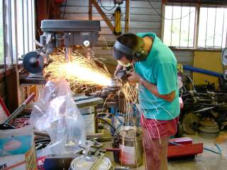
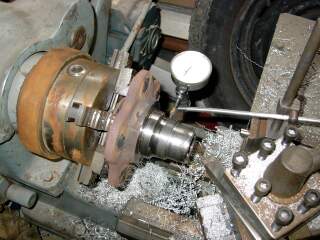
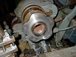
This looked easy, but we had some major problems. The tool bit in the lathe kept going blunt. After many re-sharpenings we managed to get a flat surface. To mark out the PCD (stud spacing) we scribed a line with the hub still in the lathe. The spaced out five marks with a scriber.
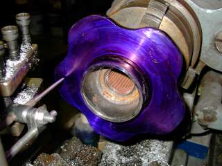
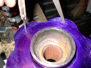
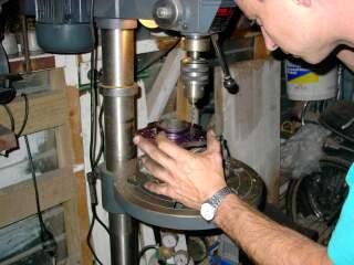
The problems we had in the lathe with the bit blunting also blunted the drills. You see, when one MIG welds to cast iron the mixture of the two metals forms a very hard metal, so hard in fact that it chips away at tool steel! This put a major dampener on the situation when we drilled the larger holes for the studs, as the drill ended up finding the softer metal and drifting off centre. Lots of hard work, all for nothing and two good hubs down the flusher. Ah well, we live and learn :-)
We managed to get 3 studs in one hub close to where they needed to be, and close enough for a wheel to bolt on so not all was lost as this meant that I could carry on and trial fit a wheel to check clearances. So we carried on drilling the Cefiro discs to the Commodore pattern which went the way I was hoping the hubs would go, nice and easy.
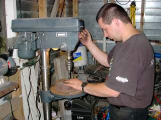
The observant may spot the lack of hair in this photo. I got sick of sweeping garage floors with my long hair so off it came!
I then got some brand spanking Bilsteins for a R32 Skyline from The Shock Shop in Wellington and fiddled with them compressing and stretching the suspension through its full motion whilst checking tyre clearances until we found the correct mounting height and position.
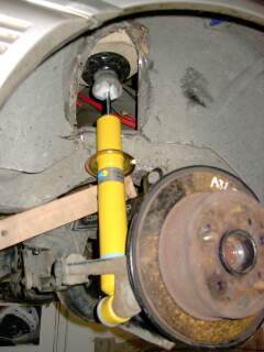
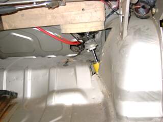
Visible on the left is the originally shock mount cut out. Again I have rotated the pics as the car is still upside down at this point
The tyre just clears the outer guard as it goes through its travel, and with full bumpstop compression, sits about 1cm off the inner guard
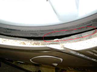
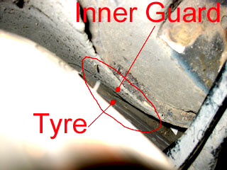
Here's a pic showing the travel and how the camber changes as it goes in and out.
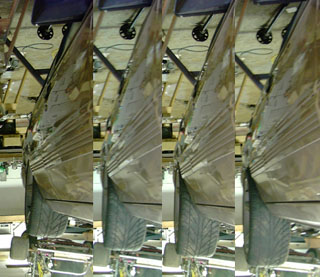
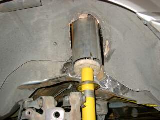
After sorting out where the strut is to go I made up some strut towers out of 5" exhaust tubing and some 3mm sheet metal. I then temporarily mounted it to check clearances for a final time.

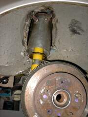
All OK? yip! Well weld the bugger in then!
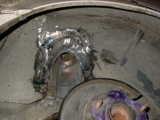
Looks a bit messy unpainted but it works! Have had the weight of the car on it and all is OK.
With the right side in, I had a bit more of an idea what to cut for the left side

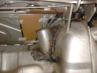
And having the right one to measure from, I made up some jigs to position it.
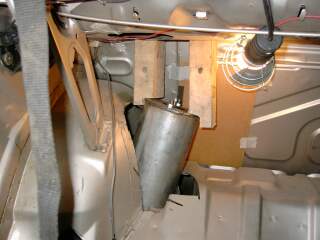
The wooden disc on the shock is a spacer that's the same diameter as a spring so that I can check if it clears
Well it took ages, but as I had sold the house, the car had to be moved. So we got cracking and mounted the left hand strut mount and installed both shocks and lowered the car back onto its wheels.
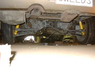
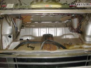
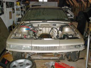
On the left - ready to be shifted, one the right - in its new location. Seeing it like this I have a bit more enthusiasm to get it running again :)
I mentioned earlier with the white faced dash that I had illuminated the satellite switches with blue LED's. I have had a query regarding this and thought I'd outline how I did this here.
First one has to take apart the switch housing, (the switch comes out of the dash with a single screw underneath) this is done easily by using a small blade or a fine flat blade screwdriver. There are two tabs, one underneath in the middle by the join and one on the top at the back by the plug. Prise the one on the bottom open first then the one at the back.
Once opened remove the small 12v globe and do with it what you wish. Also get rid of any green filters. Get your 5mm Hi Intensity Blue LED (DSE Cat# Z3902) and sand the surface of it to allow the light to disperse better. Solder it's cathode lead, (the short one) onto the negative terminal. In this case, the one with the brown wire. The Anode goes onto the positive terminal. In my case the one with the yellow wire. Cut the yellow wire off that terminal and insert a 4.7K resistor between it and the terminal like in this picture.
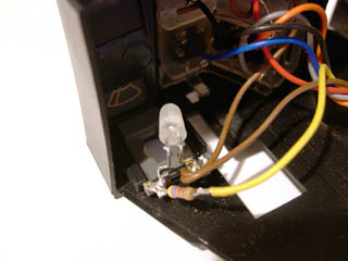
Note that I have bent my LED towards the middle of the unit to illuminate more evenly. Snap it back together and install in vehicle.
When all is done properly, this should be your result:
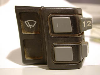
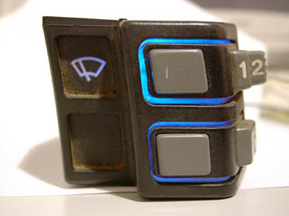
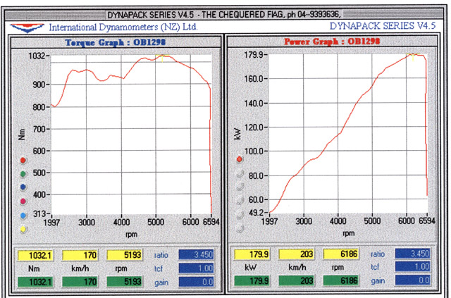
Well unfortunately due to family commitments I could no longer afford the time nor money to complete the Nismodore so it was sold to a new owner. I wish him well in getting it going. Below are the specs for the car and a printout of the one and only dyno run I did with it. Thanks for all those that helped me and viewed this build blog.
Make: |
Holden |
Model: |
Commodore - Vacationer |
Engine: |
RB25DET |
Number of Cylinders:- |
6 in line |
Capacity:- |
2498 cc |
Bore:- |
71.7 mm |
Stroke:- |
86 mm |
Compression Ratio:- |
9:1 |
Induction:- |
Nissan Fuel Injection ECCS |
Air Filter:- |
K&N Round Pod type mounted under front bumper |
Intake Manifold:- |
Standard Nissan |
Cylinder Head:- |
Standard Nissan 24 Valve Twin Cam |
Valves:- |
Standard Nissan |
Rocker Gear:- |
Standard Nissan |
Pistons:- |
Standard Nissan |
Con rods:- |
Standard Nissan |
Rod Bolts:- |
Standard Nissan |
Crank:- |
Standard Nissan |
Camshafts:- |
Standard Nissan |
Exhaust:- |
3" Dump pipe with flanged side outlet, 2.5" mandrel bent single pipe to the rear |
Ignition:- |
Standard Nissan 6 coil Electronic |
Drive Train: |
|
Flywheel:- |
Standard Nissan Cast Iron |
Clutch:- |
9.5" Standard Nissan |
Pressure Plate:- |
Standard Nissan |
Gearbox:- |
Standard Nissan 5 speed |
Ratios 1st:- |
3.592:1 |
2nd:- |
2.057:1 |
3rd:- |
1.361:1 |
4th:- |
1:1 |
5th:- |
0.813:1 |
Drive shaft:- |
2 piece |
Differential:- |
Holden 3.45:1 |
Brakes: |
|
Master Cylinder:- |
Standard Holden VB V8 1" bore double diaphragm |
Front:- |
Cross Drilled & Slotted Disc |
Rear:- |
Cross Drilled & Slotted Disc |
Callipers:- |
Standard Holden VR Front & VL rear |
Pads:- |
Ultimate front, Metal Kings rear |
Suspension: |
|
Front:- |
Standard |
Rear:- |
Standard sagged |
Wheels:- |
17"x8" |
Tyres:- |
235/45/r17 |
Performance: |
|
0-100 km/h:- |
5.7 seconds |
400 metres standing start:- |
13.71s (200m 9.14s) |
1st Gear max speed:- |
55 km/h |
2nd Gear max speed:- |
97 km/h (all these speeds are calculated |
3rd Gear max speed:- |
146 km/h based on max rpm of 6800, |
4th Gear max speed:- |
200 km/h given tyre size and ratios) |
5th Gear max speed:- |
245 km/h |
Power And Torque @ wheels:- |
180kW @ 6200 rpm - 1032Nm @ 5200 rpm |
If you have any questions, please check the FAQ here first. If there is something that doesn't answer, feel free to contact me using the contact page
View or download the RB25DET computer connections
View or download the RB25DET wiring diagram
RB-VL Rev Counter Module
